
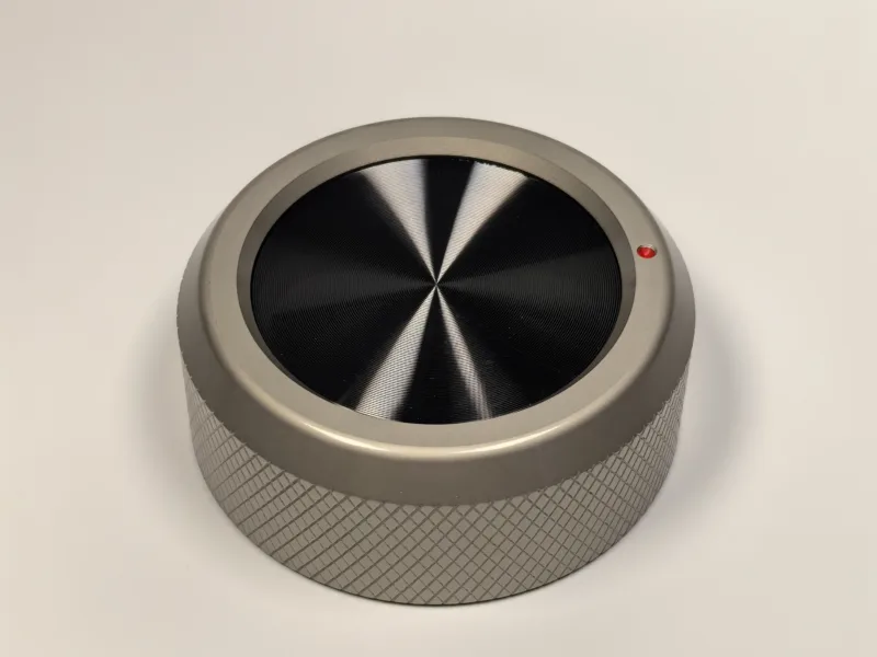
The gas stove knob shaft determines whether a knob can be assembled and turned correctly. Two knobs may look alike from the front, yet have different internal bores, insertion depths or index positions. For OEM sourcing, specify the shaft interface before approving a model, material or finish.
This guide explains what buyers should send when they need a gas stove knob to fit a valve or other appliance control component.
Quick answer: What must a gas stove knob shaft specification include?
Specify the actual shaft profile, critical cross-section dimensions, available shaft length, required knob insertion depth, retention concept and the indicator position at OFF. A dimensioned drawing is preferred; otherwise, send a mating sample and measured photographs.
What is a gas stove knob shaft interface?
The shaft interface is the connection between the control shaft and the knob’s internal bore, insert or fixing feature. It transfers the user’s rotation of the knob to the component underneath. The interface also establishes how the knob sits on the front panel and where its indicator points when the control is off.
For a broader application overview, see our gas stove and cooker knobs for OEM projects.
Common shaft profiles to identify
Do not use a profile name alone as a final specification. Measure the actual mating part and include a drawing or sample where possible.
D-shaft
A D-shaft has one flat side and one rounded side. The matching knob bore needs the correct diameter and flat geometry. In an appliance project, the flat can also affect the installed orientation of the indicator, so the off position should be shown on the drawing.
Round shaft
A round shaft is circular, but its mounting method still needs to be defined. Confirm whether the knob is retained by an insert, a set-screw feature, a press-fit arrangement or another approved method. The shaft diameter alone is not enough information.
Splined, double-flat and other profiles
Some appliance controls use splines, multiple flats or application-specific geometries. For these profiles, a close-up photograph is useful but not a substitute for measured dimensions. Send a dimensioned drawing or physical mating sample before an existing knob is considered suitable.
Dimensions that need to be on the drawing
The following information gives a supplier a practical starting point for a fit review:
- Shaft profile and a view of the cross-section
- Diameter, across-flat dimensions or spline details, as applicable
- Available shaft length above the front panel
- Required insertion depth inside the knob
- Clearance around the shaft and panel opening
- Required bore, insert or retention concept
- Rotation range and the defined off position
Where the control shaft is part of a purchased valve or switch, include the component drawing or exact component reference if it is available. This helps prevent a design from being based only on the appearance of a removed knob.
Why D-shaft fit requires more than one measurement
A D-shaft request should state both the rounded dimension and the flat geometry. It should also show how the knob indicator must align when the control is installed. A bore that enters the shaft but positions the indicator incorrectly is not an approved fit.
For a clear review, provide:
- A front-panel drawing or photo showing the control scale
- A cross-section or measured view of the shaft
- The required off position and direction of rotation
- The knob’s intended insertion depth and visible panel gap
Check the knob and panel as one assembly
A shaft interface cannot be evaluated in isolation. The knob must also clear the control panel, neighbouring knobs and appliance features such as displays or handles. Confirm the overall knob diameter and height, the space between controls and the indicator position across the intended rotation range.
When using an existing reference model, compare its published dimensions with the actual panel layout. For examples, browse our current zinc alloy appliance knobs, aluminum appliance knobs and plastic appliance knobs.
How to send a shaft sample for review
If a complete drawing is not available, send a removed knob together with a mating-shaft sample when practical. Add labelled photos that show:
- The front face and indicator
- The rear bore, insert or fixing feature
- The shaft cross-section next to a measurement reference
- The control panel and the knob’s off position
Photographs support the discussion, but the final specification should still record the critical dimensions and orientation requirements.
Gas stove knob shaft RFQ checklist
- Gas stove, gas hob or cooker application
- Control component type and, if available, component reference
- Shaft profile and dimensioned cross-section
- Available shaft length and required knob insertion depth
- Off position, rotation direction and indicator alignment
- Knob diameter, height and panel-clearance limits
- Preferred material, finish, colour and markings
- Drawing, reference sample, estimated quantity and target schedule
From shaft interface to a complete knob specification
Treat the shaft interface as the first technical check. After you define the fit, confirm the knob envelope, material, surface finish and markings. For the complete selection sequence, read how to choose an appliance control knob for OEM projects.
Frequently asked questions
Is a D-shaft name enough to order a gas stove knob?
No. The profile name does not define the diameter, flat geometry, insertion depth or installed indicator orientation. Provide the actual dimensions or a mating sample for review.
Can a knob fit the shaft but still be unsuitable?
Yes. The knob may conflict with the control panel, neighbouring controls or the required control scale. Check the full knob-and-panel assembly, including the bore.
What if the valve or shaft drawing is unavailable?
Send the removed knob, a mating-shaft sample where practical, and clear labelled photographs with measured dimensions. Record any dimensions or orientation points that still need confirmation.
Send your gas stove knob interface for review
Send the shaft drawing, a mating sample or measured photographs through our contact page. Include the appliance application, panel layout and required appearance so the shaft interface and knob design can be reviewed together before project terms are confirmed.